For any physically-intelligent mobile robot that operates autonomously in the real world, successful navigation is a critical capability. This requirement of the topic is also highly relevant across various sectors, including logistics, autonomous driving, and search-and-rescue applications. Furthermore, advanced robotic tasks, such as object manipulation, often depend on the foundational stability provided by accurate navigation. While the specific solution approach must adapt to environmental parameters (such as indoor/outdoor or known/unknown maps), all effective systems fundamentally rely on robust path planning. Based upon the foundational concepts of robotics, such as planning methods (Bug1 and Bug2), this guide provides a comprehensive, yet accessible, depiction of mobile robotics with a demonstrated 2D example. Using the popular ROS2 framework and C++, we will explore the core ideas needed to manage basic wheeled robot navigation in a simulated 2D environment to reach a goal while avoiding obstacles, explaining the theory as well as the code.
----------
**Table of Content**
----------
[TOC]
----------
# Introduction:
Autonomous Mobile Robots (AMR) have many applications in many fields, which is why it is also important part of robotic. Currently many startups are working on solutions to use AMRs in sectors like:
- Logistic: Moving goods in warehouses with robots is already implemented in many places.
- Farming: Controlling and monitoring the fields, possibly also reaping is applied also.
- House chores: Autonomous Vacuum Cleaners have been available commercially.
The task at hand in the example here seems quit simple: navigation towards a known goal, while avoiding obstacles. As shown in Figure 3 below. However, as soon we start to analysis the task in a real-world applicable way, it turns out to be quit complicated. For instance:
- How the robot senses the environment
- How the robot is controlled (by speed, relative or absolute position)
- What is the movement possibilities of the robot.
- How exactly to plan the path around obstacles.
- How to synchronies the sensing, controlling and planning of the robot
These questions also occur in many other autonomous mobile robots (AMR) projects. Here, we will start by answering some of these questions in our example, while leaving others for future posts.
One popular tool helping with these common building questions is the framework of Robotic Operating System 2 (ROS 2). In ROS2, the communication middleware, between the controlling, planning and sensing parts are handled automatically and securely. This save a lot of time for the developer, let alone the huge community around ROS2 tools and package, where you can find implementations for many popular robotic alogorthems.
To put in other word, ROS 2 is the "most widely" (my own confident claim) adapted common language of robotic. So if your project is in ROS you can expect more readership (or collaboration), or if you're fluent in ROS you have capability of reading many other projects. It can be said also that ROS2 is package manager for many robotic tools (including hardware drivers).
In ROS2 you can use multiple languages to write your code; however, C++ is the most popular/efficient option to work with. If you ever worked with interpreted languages like Python, Matlab, you can see it is much easier to develop with. However, the problem of using them for robotic projects (and many other performance-sensitive applications), is their simplification of the underlying processes. In robotic, you want to use your memory/compute power wisely. Even if your hardware is powerful, making your programs faster can also make your robot more efficient.
## The Current Navigation Task
As one of the most important tasks in mobile robotics, navigation, is the main purpose for an autonomous mobile robot. Where doing it safely and efficiently while fulfilling its objective are usually the main criteria for successful navigation.
In navigation the inputs are the sensor stream of data, be it its lidar scans, RGB camera frames or even the wheels odometry data. The output, however; is mainly the navigation movement commands, which should be planned for the whole task at global level, while also taking care of the necessary local changes like obstacle avoidance. These plans require knowledge of the robot position (localization) and its surroundings (mapping), and then they can be used to define the future trajectory of the robot.
These are basically the main tasks for any mobile robot. However, the exact setup, containing for instance, the sensors resolution, the actuators flexibility, the computational power, and the actual task at hand will determine what tweaks and adaptions are needed to address these steps.
### The simulation idea
As a first starting demo here, our goal will be quite simple: defining a goal in 2D simulated environment and then navigating towards that goal. Here we are simulating all of the sensors, actuators and environments, all as 2D only, as shown in the figure below.
Note
This last assumption actually isn't that outrageous, as ground mobile robot on flat level operate in terms of two dimension (unless there's stairs or it's not always flat) and they will rarely require the third altitude dimension.
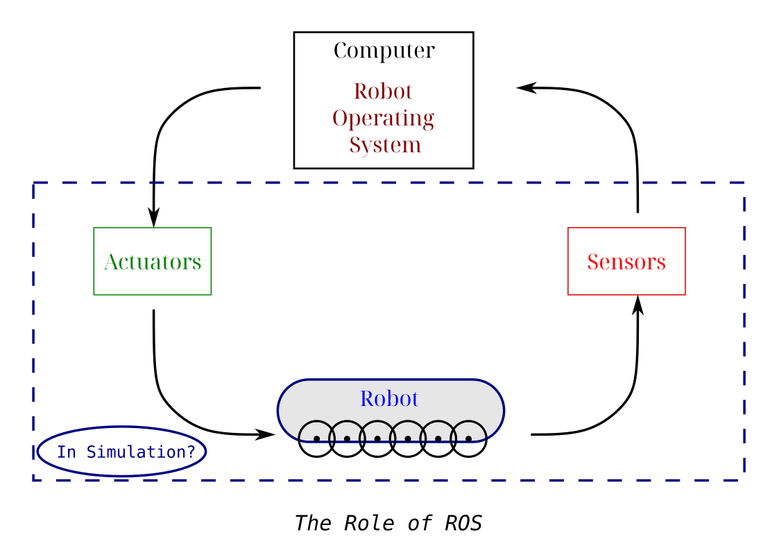
Figure 1: The main modules for mobile robotic ROS project.
As you can see in the image below, beside setting random destination point in the environment (the blue circle), we are also scattering randomly obstacles (shown as green boxes) to make the task more challenging, and imitate the obstacle avoidance task.
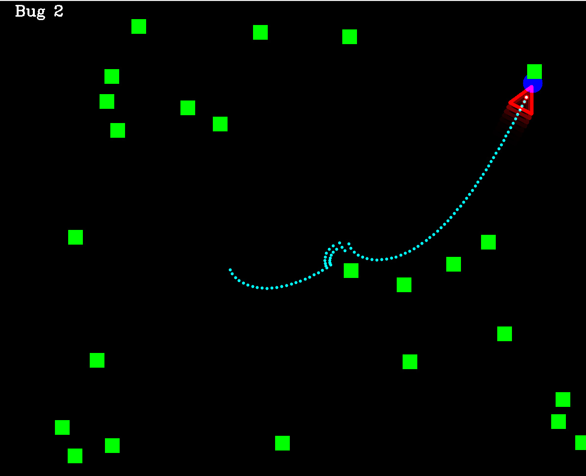
Figure 2: The simulated 2D environment in this project for reaching a destination point.
The graphics in this projects are utilizing the popular OpenCV library in C++.
### The bicycle model
After defining the simulation environment, it is important to define the exact robot state under control. This actually depends mainly at what kind of actuators we have, for instance we can send the next point coordinates (x,y) as the output command but then it should be converted to actual wheels speed of rotation and direction utilizing another movement model. This may introduce another type of errors due to the extra conversion step, so we prefer here to use the speed $v$ and wheels relative heading angle $\gamma$ as the direct and actual controlled signals.
However, to simulate the exact movement of the robot given its forward speed and front wheels heading, the literature proposes an approximate model called "the bicycle model" for car-like wheeled robots, where we can, as shown in the figure below, calculate the update of the robot position and heading, given these signal commands.
On the other hand, as drawback, this model ignores the wheels slipping and friction, which also introduce errors in controlling the robot.
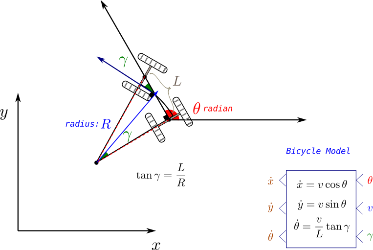
Figure 3: The bicycle model for wheeled car-like robot.
### Primer on Path Planning
As mentioned previously, the task to be solved in AMRs are threefold: localization, mapping and planning. As an initial tutorial, the focus here will be merely on the planning part (while leaving the other two for future posts), in other words:
We will assume here full knowledge of the robot pose, as well as its surroundings. What it is left is defining its speed and rotation that it should take in every step to reach its destination.
This task is known as path planning, and it is solved in a variety of ways in the robotic field, including: graph search, reinforcement learning, or force fields vectors.
Below, here we will have a quick general look on these types of methods. The only implemented method here will be the Bug 2 method: a classical goal-based planning algorithm. Future posts will include more implementations.
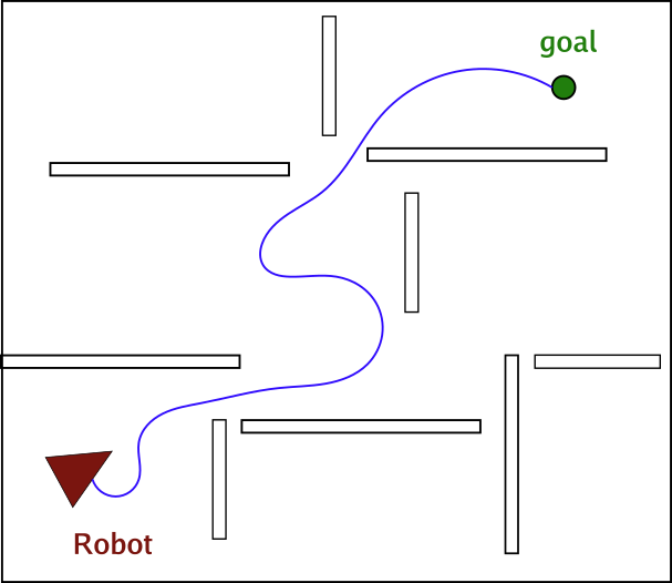
Figure 4: an example for the path planning towards a destination while avoiding obstacles (the trajectory in blue is the needed output).
As the figure above shows the task in path planning is to find the robot movement trajectory (series of x,y coordinates) to reach the destination while avoiding collision with obstacles. It is also desired in path planning method to seek the shortest path to the destination, or more generally the cheapest path, where the cost can be related to avoiding certain places more than the distance.
| Method |
Explanation |
Example |
| Classic |
This has lead to algorithms that depend on basic logic like following the line of sight from position to goal while following a maneuver around obstacle. |
Bug 1 and 2 |
| Graph-based |
Later, graph search algorithms shown to be good candidates for many situations, where the environment plane is segmented to cells in a grid-based manner, which distinguish between passable and obstacle cells, forming a map known as occupancy grid. |
Breadth-first search, A*, D* |
| Feasible Planners |
However, all these methods ignore the movements constrains of the robots, for instance a robot that can only move forward, cannot make a backward movement, or in some cases cannot turn in place. Therefore the planned path should take that into account. This has motivated another set of methods that can guarantee feasible movements paths. |
Dubins Path and Lattice planners |
| Probabilistic and Roadmap Planners |
Lastly, for a robot in a dynamic environment, where the destination is on the move (always changing), graph-based planning (which forms a cost map related to that destination) won't be suitable due to the need to recalculate every time, which require constant recalculation. Therefore, probabilistic methods or roadmap methods, like Rapid Random Trees (RRT) were proposed to enable the planning between any two point in the given environment. Practically these methods were more efficient in generating any path without conditioning on start or end point of the path. |
Rapid Random Trees, Probabilistic Planners |
# The Coding Part
After getting an initial view over the theoretical side, we start here by the actual code in ROS and C++.
In the following we will implement the main navigation program (in 2D simulator) from scratch, utilizing Bug 2 planning algorithm and bicycle model for the robot movement as a demonstration example.
First, we will provide a very short but comprehensive introduction to ROS2, its installation and main key concepts (for more on that check the amazing ROS documentation at ros.org). Then we will go over how to structure and create the project with it, and how to design its data interfaces.
Next, we will go over the main program skeleton, which will be a node graph in ROS. We will keep it generic for now, but other alternative, certainly exist. After that we will explain the Bug 2 planner code, followed by ways to run the full project either in multiple terminals or as a launch file.
Last but not least, a template for a ROS node written in C++ will be showed and analyzed, followed by some failure cases the program still suffer from, and warping up with the main conclusion from the post.
## Installing ROS
We're using here ROS2 Jazzy release, which still the current maintained version in the time of writing for Ubuntu 24 operating system.
For any other ROS version, just replace the `` part of the installation code below, with its name, in order to install it.
```bash
sudo apt install ros--desktop
sudo apt install ros-dev-tools
```
This will install ROS in your computer, to test it, you can run a demo program, installed by default with the following commands:
```bash
source /opt/ros/jazzy/setup.bash
ros2 run turtlesim turtlesim_node
```
The source step is necessary every time a ROS command should be run, so it make sense to add it to the startup script of your terminal (namely: `.bashrc`)
## Core concepts of ROS
ROS is considered a middleware framework in robotic, as it links the underlining hardware drivers and communication protocols to higher level sensor and actuator data processing. Among its main advantages we mention:
- Better communication between robotic functionalities
- Better collaboration (unified popular framework)
- Huge open source library of popular algorithms
Upon a general view of ROS programs we note that it contains the following main concepts:
- **Nodes**: they represent the building stone of ROS program, where each node will be responsible for a task or even a step in the algorithm.
- **Topics**: With them, nodes can exchange data among each other in a publisher/subscriber scheme: there could be many subscribers to one publisher but not the other way around
- **Services**: When the data exchange is viewed as command to perform one task in client/server scheme, using a service will be more suitable
- **Actions**: When the service being performed is extending over large time period, (as in the action of going after a destination), and there is a need to follow up with the status of this service regularly, then utilizng the action template will be the ROS-compatible option in this case.
## Creating the package in ROS
For any project in ROS2, we note a specific folder structure that should be followed. This main hierarchy of any ROS2 project contain the following levels:
- Workspace level (belongs to the full robot platform of hardware, where any project using it can be theoretically written there)
- Package level (the full intended application you're doing on that specific robot)
- Node level (the exact functionalities undertaken to achieve the application)
Think of these levels as organizational structures that make the project more readable.
So in our case, we need one workspace, maybe one or two Packages (for organizational purposes only, as we're doing one project so far), and multiple nodes. We will also be using only topics as means of communication, although services and actions can also be used here, we will leave them for future posts.
### Creating the project directories
So now, we are ready to start writing the project. We start here by creating the empty project directories, as follows:
```bash
$ source opt/ros/jazzy/setup.bash
$ mkdir amr_ws
$ cd src/
$ cd ..
$ colcon build // always at ws level
$ source install/setup.bash
```
`colcon` is the building command in ROS2 (equivalent to CMAKE in C++). Additionally, we see the need to source the project setup script after each build, in addition to main ROS setup.bash script.
Then we create the package (as C++ package):
```bash
$ cd src/
$ ros2 pkg create planners_pkg --build-type ament_cmake --dependencies rclcpp
```
For C++ projects we need the following build type `--build-type ament_cmake ` and dependency `--dependencies rclcpp`.
Great, now that we have the empty package, we can create our first node:
```bash
$ cd amr_ws/src/planners_pkg/src
$ touch planners.cpp
```
From here you can edit your node code in `planners.cpp`. For the change to take effect you need to build the whole package again (with `colcon`) and source the project once more.
To run the node afterwards use the following (possibly under `alternative_name):
```bash
$ros2 run planners_pkg planners --ros-args -r __node:=alternative_name
```
We can check if the code is running, by typing `ros2 node list`. We can also check the status of a specific topic by typing the following also:
```bash
$ ros2 node list
$ ros2 node info /topic_name
```
Other command that helps debugging and viewing topics info are:
```bash
ros2 topic echo /topic_name
ros2 interface show example/interface
ros2 topic pub -r 2.0 /topic_name interface "{key: value}"
```
The first command shows the content of a topic messages
The second shows the structure of topic messages (called interfaces)
The last command shows how to publish new topic with a given name from command line just for debugging purposes.
## Used interfaces
We mentioned interfaces, which are integral part of defining topics, namely they define the data structure that will be sent as message in the topic, service or action. So it is important to choose them wisely. ROS provide a variety of interfaces definitions for various purpose, but in some cases creating a new custom interface maybe needed.
In the project here, we will need mainly to send the following messages:
- Control commands: for that we will use here Twist messages. Can viewed by the command below:
```bash
yasin@yasin-B650M-D3HP:~/Dokumente/blog/Site_2$ ros2 interface show geometry_msgs/msg/Twist
# This expresses velocity in free space broken into its linear and angular parts.
Vector3 linear
float64 x
float64 y
float64 z
Vector3 angular
float64 x
float64 y
float64 z
```
- Robot pose: As we have 2D pose only (consisting of x,y and $\theta$ coordinates), we will use Pose 2D messages (although it is deprecated)
```bash
yasin@yasin-B650M-D3HP:~/Dokumente/SideProjects/housekeeper_ws/src$ ros2 interface show geometry_msgs/msg/Pose2D
# Deprecated as of Foxy and will potentially be removed in any following release.
# Please use the full 3D pose.
# In general our recommendation is to use a full 3D representation of everything and for 2D specific applications make the appropriate projections into the plane for their calculations but optimally will preserve the 3D information during processing.
# If we have parallel copies of 2D datatypes every UI and other pipeline will end up needing to have dual interfaces to plot everything. And you will end up with not being able to use 3D tools for 2D use cases even if they're completely valid, as you'd have to reimplement it with different inputs and outputs. It's not particularly hard to plot the 2D pose or compute the yaw error for the Pose message and there are already tools and libraries that can do this for you.# This expresses a position and orientation on a 2D manifold.
float64 x
float64 y
float64 theta
```
- Images of the environment: for that we will use image messages
```bash
yasin@yasin-B650M-D3HP:~/Dokumente/SideProjects/housekeeper_ws/src$ ros2 interface show sensor_msgs/msg/Image
# This message contains an uncompressed image
# (0, 0) is at top-left corner of image
std_msgs/Header header # Header timestamp should be acquisition time of image
builtin_interfaces/Time stamp
int32 sec
uint32 nanosec
string frame_id
# Header frame_id should be optical frame of camera
# origin of frame should be optical center of cameara
# +x should point to the right in the image
# +y should point down in the image
# +z should point into to plane of the image
# If the frame_id here and the frame_id of the CameraInfo
# message associated with the image conflict
# the behavior is undefined
uint32 height # image height, that is, number of rows
uint32 width # image width, that is, number of columns
# The legal values for encoding are in file include/sensor_msgs/image_encodings.hpp
# If you want to standardize a new string format, join
# ros-users@lists.ros.org and send an email proposing a new encoding.
string encoding # Encoding of pixels -- channel meaning, ordering, size
# taken from the list of strings in include/sensor_msgs/image_encodings.hpp
uint8 is_bigendian # is this data bigendian?
uint32 step # Full row length in bytes
uint8[] data # actual matrix data, size is (step * rows)
yasin@yasin-B650M-D3HP:~/Dokumente/SideProjects/housekeeper_ws/src$
```
- Destination coordinates: We will be utilizing Vec3 interface (where z is always ignored)
```bash
yasin@yasin-B650M-D3HP:~/Dokumente/SideProjects/housekeeper_ws/src$ ros2 interface show geometry_msgs/msg/Vector3
# This represents a vector in free space.
# This is semantically different than a point.
# A vector is always anchored at the origin.
# When a transform is applied to a vector, only the rotational component is applied.
float64 x
float64 y
float64 z
```
There are many other built-in interfaces. To view them all, and choose a suitable one from then, you can run:
```bash
$ ros2 interface list
```
This command will show also interfaces for the services and actions as well.
## Main code skeleton of a Node and its publishers/subscribers in C++
After defining what the input and output message structure for each node will be, we need to start implementing the logic in code, namely by executing the following steps for ROS2/C++ program:
1. Create the node file inside the package `\src` directory, as a file with `.cpp` extension. If your code is big or need to be used elsewhere as well, use additional `.hpp` files and include them in the `.cpp` file.
2. Give the node file and the node instance class representative names reflecting what they actually do, like Planner/Robot Model, etc.
3. Write the exact code to implement your logic. As an example, we view below the basic template for our robot_model node to demonstrate the main part of a functioning node:
```c++
#include "rclcpp/rclcpp.hpp"
#include "geometry_msgs/msg/pose2_d.hpp"
#include "geometry_msgs/msg/vector3.hpp"
#include
#include
#include
#include "utils_funs.hpp"
// maybe receive twist message to change position
class Robot: public rclcpp::Node
{
public:
Robot(int H, int W, int RobotSize):Node("robot_model") {
std::printf("Robot is created");
sub_ = this->create_subscription("robot_commands",10,
std::bind(&Robot::update_model,this,std::placeholders::_1));
pub_ = this->create_publisher("robot_pos",10);
pos = getInitialPos(W,H,RobotSize);
old_pos.assign(pos.begin(), pos.end());
pose_.set__x(pos[0]);
pose_.set__y(pos[1]);
pose_.set__theta(pos[2]);
//location_.header.stamp = this->now();
RCLCPP_INFO(this->get_logger(),"built");
timer_ = this->create_wall_timer(std::chrono::milliseconds(40),
std::bind(&Robot::send_location,this));
}
void update_model(const geometry_msgs::msg::Vector3::SharedPtr message){
// update based on bicycle model
double gamma_rel = message->x*M_PI/180;
double speed = message->y;
double dtheta = (speed*(tan(gamma_rel))/RobotSize);
double dc = speed * std::cos(pos[2]+dtheta);
double dr = -speed * std::sin(pos[2]+dtheta); // y-axis is reversed
//dr = 0, dc=0;
old_pos.assign(pos.begin(), pos.end());
std::cout << dr << " " << dc << " " << dtheta << std::endl;
pos[1] = pos[1]+dr;
pos[0] = pos[0]+dc;
pos[2] = pos[2]+dtheta;
std::cout << pos[0] << " " << pos[1] << " " << pos[2] << std::endl;
this->send_location();
}
void send_location(){
this->pose_.set__x(this->pos[0]);
this->pose_.set__y(this->pos[1]);
this->pose_.set__theta(this->pos[2]);
//this->location_.header.frame_id = "0";
//this->location_.header.stamp = this->now();
pub_->publish(this->pose_);
//RCLCPP_INFO(this->get_logger(),"Callback is called");
}
void reset_pose(){
pos.assign(old_pos.begin(), old_pos.end());
}
private:
geometry_msgs::msg::Pose2D pose_;
rclcpp::Subscription::SharedPtr sub_;
rclcpp::Publisher::SharedPtr pub_;
rclcpp::TimerBase::SharedPtr timer_;
// TODO double or int?
std::vector pos;
std::vector old_pos;
int RobotSize = 50;
};
int main(int argc, char **argv)
{
rclcpp::init(argc,argv);
auto node = std::make_shared(1200,1200,50);
rclcpp::spin(node);
rclcpp::shutdown();
return 0;
}
```
4. Update your `CMakeLists.txt` as follows, to instruct it for building the new node:
```cmake
cmake_minimum_required(VERSION 3.8)
project(planners_pkg)
if(CMAKE_COMPILER_IS_GNUCXX OR CMAKE_CXX_COMPILER_ID MATCHES "Clang")
add_compile_options(-Wall -Wextra -Wpedantic)
endif()
# find dependencies
find_package(ament_cmake REQUIRED)
find_package(rclcpp REQUIRED)
find_package(geometry_msgs REQUIRED)
find_package(nav_msgs REQUIRED)
find_package(sensor_msgs REQUIRED)
find_package(cv_bridge REQUIRED)
find_package(image_transport REQUIRED)
find_package(OpenCV REQUIRED )
include_directories( ${OpenCV_INCLUDE_DIRS} )
include_directories( include/${PROJECT_NAME}/ )
# first node: robot
add_executable(robot_model src/robot_model.cpp )
ament_target_dependencies(robot_model rclcpp geometry_msgs )
add_executable(env_model src/env_model.cpp)
ament_target_dependencies(env_model rclcpp geometry_msgs nav_msgs cv_bridge sensor_msgs std_msgs image_transport OpenCV)
add_executable(planner_node src/planners.cpp)
ament_target_dependencies(planner_node rclcpp geometry_msgs sensor_msgs std_msgs image_transport)
install(TARGETS
robot_model
env_model
planner_node
DESTINATION lib/${PROJECT_NAME}/)
```
5. Build the package by running: `colcon build` from the main workspace folder (will build all packages by default) or with `--package-select` to build one package, source again and test the new build:
```bash
ros_workspace/$ colcon build --package-select the_needed_package # shows the modified package
ros_workspace/$ source install/setup.bash
ros_workspace/$ ros2 run pkg_name node_name
```
## Sketching the nodes network
The following figure depicts the general idea for the program, with its important parts (usually needed for any real robots) being the controlling logic and the mapping part, along with other hardware drivers for the sensors and actuators devices. As we are here modeling the environment as well, we need nodes to represent both environment and robot models.
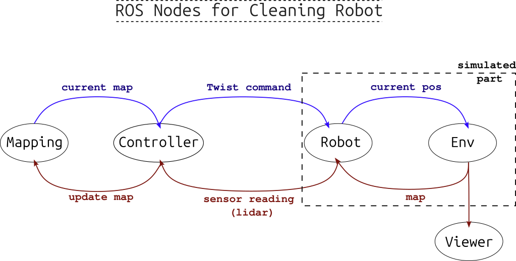
Figure 5: A sketch of ROS mobile robot graph: Mapping and Planning are separated steps.
In our example, after running all the nodes, we can view the graph showing the nodes and their published or subscribed-to topics with the command: `$rqt_graph`, which will give figure below.
Note that in addition to the three main nodes (robot mode, environment model, and planner), we are using image_view node from another built-in ROS package called **image-tools** (installed by default). Additionally, we don't use a mapping node here, as we assume a simple case with a complete knowledge of the static environment. In future iterations of this project we will add mapping capabilities.
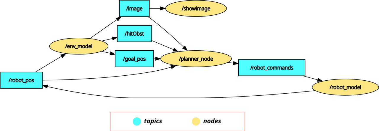
Figure 6: The output from rqt_graph when running the project, showing the nodes and topics.
Note also that what we are using in the `planner_node` are only the goal and robot poses, in addition to a boolean flag indicating whether an obstacle has been hit. Although the image of the scene topic is subscribed to, it is not actually used by the planner function.
From the graph we note that a synchronization between the nodes is necessary to ensure the validity of data (values calculated for a specific time point comes from that point too): therefore the robot model node sets the frequency of computing where the rest of the nodes depend on receiving a certain topic message they are subscribed to, that triggers their calculation cycles.
In the next subsection we will focus on the planner node logic, namely its implementation of Bug2 method.
## Bug 2 Algorithm Steps
For the purpose of this basic example, we will be starting with basic Bug algorithm. In **Bug 1** algorithm (see reference here), the steps are simple, namely as the following sequence shows below:
1. Define the vector from the robot position towards the destination position and guide the robot along it
2. When the robot encounter an obstacle, it inspects its boundaries in both direction, then determines the nearest point to the destination and move towards it.
3. It then recalculates the direction vector and resumes following it until it reaches a set proximity of the destination.
This method seems quit simple but it main importance comes from the exact definition of the algorithmic logic of executing those steps. Later this algorithm was improved in **Bug 2** where the inspection of the obstacle boundaries (in step 2) was carried out from a single direction only /left or right/, not both. This leads to faster maneuvering around obstacles and cheaper/shorter routes.
The Gif shown at the start of this post, shows a demonstrated implementation of the idea of Bug 2 and what its path might look like.
In the code part below, we show the function implementing the path planning part of our project. Mainly it consists of 3 steps:
- Finding the **movement vector**: `diffx, diffy, targetT`
- Finding the **rotation difference** between the robot and that vector (which needs to be restricted between $\pi$ and $-\pi$): `dirDiff`
- Lastly sending the rotation and movement commands, where:
- The rotating is related to the rotation difference + the existence of obstacles: `act.x`.
- The movement speed is **constant forwards-always** unless it faces an obstacle then the robot goes **backwards**: `act.y`.
*Note: some robots cannot drive back, so in our case, it is assumed that it can*
```c++
void plan_bug2(const sensor_msgs::msg::Image::SharedPtr message){
// update based on bicycle model
// Step 1: find direction vector
double diffx = goal_pos[0] - robot_pos[0]; //NOTE: robot can be older than simulation
double diffy = goal_pos[1] - robot_pos[1];
// Step 2: find difference of direction rotation and transfer it to range [-pi,pi]
float targetT = atan2(-diffy,diffx)*180/M_PI;//sin axis is reversed
double dirDiff = (int)(targetT-(robot_pos[2]*180/M_PI))%360; // range between -2pi, 2pi
dirDiff = dirDiff -((180dirDiff)*360); // now range is -pi,pi
// Step 3: set rotation speed (with obstacles turn by +25 degree),
// with fixed linear speed (with obstacle)
this->act.x = (dirDiff*0.5)+(hitObst*25);
this->act.y = 10-(hitObst*30);// always fixed (to test)
this->send_command();
}
```
## Running the full program
After writing the code for all the nodes shown in Figure 6, we can run the full project by starting all the involved nodes together so they start exchanging data through topics and services and operating the different functionalities of the program.
This can be done in two ways:
- By running each node in its own terminal. We do that by sourcing the project in each terminal then running the command:
> ```ros2 run pkg_name node_name --ros-args -r __node:=alternative_name ```
- replacing the `pkg_name` and `node_name` with the package and the node names respectively.
- Or by running one launch command that starts all nodes together in one terminal. This command requires launch file, which could be either a python file or an `.xml` file.
For our source code, we utilize an `.xml` launch file (written in its own package for better organization), as follows:
```xml
```
Which looks quit simpler than the python script alternative. Note that `showimage` node requires different package (`image_tools`).
To run this file, the command will be (after sourcing the project):
```bash
$ ros2 launch planners_launch planners.launch.xml
```
It is as simple as that.
## Failure Cases
While many of the experiments end successfully, where the robot reaches the destination within a specific radius, some cases show inability or difficultly for the robot to reach its destination, namely where:
- A sharp turn should be taken by the robot to the destination point, which cannot be performed. This leads to following circular path around the destination, never reaching it, as shown in the image below.
Figure 7: A case where the robot get stuck turning around the destinations without reaching it, as this will require bigger turning curvature that the robot maximum turning capability.
- Avoiding obstacles by following the wrong direction. As Bug 2 takes always one fixed direction to maneuver around an obstacle regardless which one is faster, it cannot grantee the shortest path.
- Lastly, our exact controlling method for avoiding obstacles is not optimal. Namely, when facing an obstacle, the robot backs up and turns, but only for one step. Other manuevers, like turning inplace (if possible) or backing for multiple steps in parallel line to the obstacle boundary should result in better path.
# Conclusion and Next Steps
Awesome! by now the main ROS2 project structure with a minimal 2D example (along with its own simulated environment) is completed. Don't underestimate that, as it represents the ground work for any mobile robotic task: A* planning, Reinforcement Learning planning, Localization and Mapping. Additionally, ROS2 and C++ themselves are considered industry standard for robotic projects. Feel free to comment with questions or feedback, I'll be glad to answer. The next post, will be about continuous integration and deployment (CICD) of this project utilizing Gitlab automated jobs.
Let's connect: [Medium](https://medium.com/@mryasinusif)| [Linkedin](https://www.linkedin.com/in/engyasinyousif/?originalSubdomain=de)| [Twitter](https://x.com/YasinYousif001) | [Contact Form](https://www.rlbyexample.net/pages/contact-form/index.html)
*All images are generated by author unless otherwise stated*